
I was a Moderator at the FE Forum (Fordfe.com) for several years. A Frequently Asked Questions (FAQs) section was needed so those topics would not require the members to post answers to things well understood. In many cases this provides those answers. For some topics a link is provided to the answer. Since that time I have added addition topics here.
The topics to the left are arranged in alphabetical order.
Two font styles are used. This font is used for topics which have a specific or provable answer, such as Automatic Transmission ID.
This font is used for topics, such as the meaning of FE, that are debatable or which there is not agreementd on the answer.
390 to 410 Conversion Next Topic Top
 This conversion is not hard to do. The parts required are:
- 410/428 Crankshaft
- 410 Pistons
- 410/428 Flywheel/flexplate
Understanding why only these parts are requires (how it works) is more of a challegne. At the right is a drawing of a cylinder with the block height, deck height, piston height (usually called compression distance), rod length, crank offset and stroke identified. Of these piston height is the one we will look at first.
Piston pin height or compression distance is the distance from the center of the piston pin to the top of the piston. This distance is the amount of piston, in inches, that is above the center line of the piston pin. If the stroke is lengthened then the piston is pushed higher in the cylinder unless we decrease the pin height or change the rod length. Ford chose to decrease the pin height.
When Ford increased the stroke to make the 410 they changed the crankshaft and the piston pin location (made the pistons shorter). The chart at the right shows the original dimensions and the revised dimensions. Notice that only the stroke and piston height changed. The rod length stayed the same, as did the deck height. (The reason the pin height only changes by 0.100 inches and not the complete 0.200 inches of the stroke increase is that the piston moves further down, 0.100 inches, the cylinder as well as further up, again 0.100, the cylinder.)
Ford could have changed the rod but they did not. All rods for the 390, 406, 410, 427 and 428 and the same length - 6.49 inches.
In order to correctly balance the engine with the pistons moving further up the cylinder bores, Ford added weight to the flywheel/flexplate. All 410 and 428 engines use the same externally balanced flywheel/flexplate. Note that all harmonic balancers are neutral balanced for the FE engines and therefore interchangeable.
(The Super Cobra Jet (SCJ)has a special front crankshaft spacer to offset its heavier connecting rods. This spacer is usually referred to by its shape - hatchet. The use of the hatchet will create an unbalance problem and should be avoided unless you are building a numbers correct 428 SCJ.)
Note: although 406 and 428 share the same bore, you cannot make a 406 by using a 3.78 crank and a 428 piston. The difference is the wrist pin height. The 428 piston will sit down in the cylinder 0.100. With the standard 428 dish piston you are end up with about a 7.5 to 1 compression ratio.
The use of the longer 352 rods often pops up in threads about the 390-410 conversion. The length of the 352 rod is 6.54 inches vice the 6.49 inches of the 390-406-410-427-428 rod. The longer length of 0.050 inches results in the standard pistons sticking out of the cylinder by 0.020 inches as the chart to the right shows. Milling the tops off the pistons has been done but usually results in a compression ratio that is too high for today's regular gas.
The Emissions 390 topic discusses another use for the 410 piston.
Automatic Transmission ID Previous Topic Next Topic Top
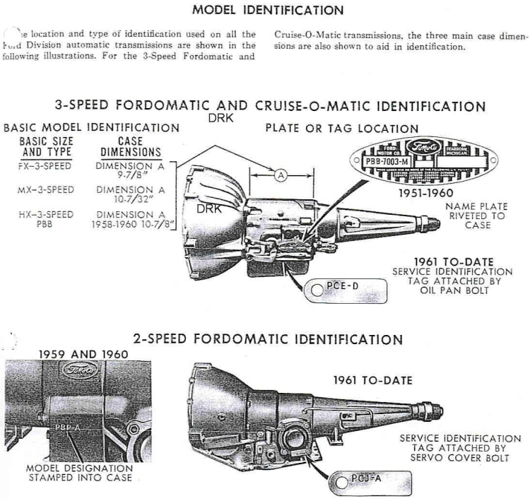
Starting in 1958 Ford used Cruise-o-Matic as a generic term for all of their 3-speed automatic transmissions. Thus, unfortunately, FX, MX, C4 and C6 were all marketed as a Cruise-O-Matics when they came out. This still causes lots of confusion when people read old owners manuals or sales brochures. Most people are referring to the FX or MX when they say Cruise-o-Matic but of course while that is correct it is not complete. The FX and MX were discontinued in 67 and in 68 they started making an FMX. The C6 came out in 1966 and they were made at the same time as the FX and MX. Specifically, the FX started in 1951 model year and ended in 1968 and was built at the Fairfax Trans Plant. The MX started in 1955 model year and ended in 1972, built at the Livonia Trans Plant. There were many non-domestic, truck, and industrial applications of the MX trans. The FMX started in 1968 model year and ended in 1979, also built at Fairfax.
The C6 does not refer to 1966. As some may recall, the original name of the C4 was XP and the C6 was XPL. If you are familiar with the Bordeaux C3, it came out for Europe in 1973. The C5 came out in 1982. The transmission "families", based on their planetary gear set design, determines whether it named with a "C" or an "X" - "X" Family = Ravigneaux design and "C" Family = Simpson design.
C-6 has a one piece aluminum bell housing and case with either a short or long aluminum or cast iron extension housing depending on application. The C6 bell housing bolt pattern depends on which engine series it bolts to. Also, there was a short tail housing version for trucks, possibly could come with a slip yoke, or most likely with a bolted on flange. Cast iron extension housing were used with some CJ's, and PI's. Some short output 4WD versions bolted directly to the transfer case, with an adapter. The 4WD version uses a different pan in some applications.
Cruise-o-Matic was comprised of 3 pieces - bell housing, case and extension housing. Cruise-o-Matic case is cast iron, with aluminum bell housing. Pans are not interchangeable. (2nd gen., short nosed three-bolt starter can be fitted to earlier Cruise-o-Matic by using a C6 flywheel.)
The following two images will help you ID your transmission:
Bell Housings Previous Topic Next Topic Top
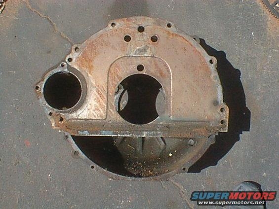
Note for the small block engine family: an increase in the number of bell housing bolts was made mid-year 1965; the early (1962 to mid 1965) engines have a 5 bolt bell housing. The late (mid 1965 and up) blocks have 6 bolts. The above image shows the later, six bolt bell bousing.
What does an FE bell housing with the following casting number: C5TA - 7505 - B (could be C6TA) fit?
You have a truck bell housing. The C5TE bell housing is .625 deeper than the car bell housings. They work fine for small block toploaders. If you have a big block toploader you will need a C6AE-D bell housing or equivalent. They need to look for a hump to indicate it will except the big clutch. The truck bell housing accepts the big clutch. Other FE bell housings are C3AA, C5AA, C5AA, C6OA, C6OZ, C8AA, C8OA, and C9AA.
A Shelby would use a regular Mustang/Fairlane bell housing. It is cast iron, marked C6OA and has a big Z on it.
Block Changes Previous Topic Next Topic Top
There are three major changes to all FE engines. 1) The thrust bearing for the crankshaft was modified in 1963 so there are two versions of crankshafts and main bearing sets. 2) A boss was added to mount the alternator in 1964. 3) The number of holes for the motor mounts was increased form two to four in 1965.
High Performance Blocks
 The early HP blocks actually had HP cast in the front of the block. The HP version
of the FE block first appeared in 1960 with the 360 HP 352 and these blocks were not drilled for hydraulic
lifters. The HP block got cross bolted main caps in 1963 about the time that the 427 engine was
introduced. While some four bolt main cap 406 blocks were produced, they are rare. All late
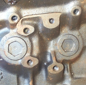
406 blocks (C4AE) and some standard blocks were also cast with provisions for cross bolting. These
provisions are just a knob at each web as shown in the phot at the right. These knobs allow the block
to have the factory style cross bolted main caps fitted.
The early HP blocks actually had HP cast in the front of the block. The HP version
of the FE block first appeared in 1960 with the 360 HP 352 and these blocks were not drilled for hydraulic
lifters. The HP block got cross bolted main caps in 1963 about the time that the 427 engine was
introduced. While some four bolt main cap 406 blocks were produced, they are rare. All late
406 blocks (C4AE) and some standard blocks were also cast with provisions for cross bolting. These
provisions are just a knob at each web as shown in the phot at the right. These knobs allow the block
to have the factory style cross bolted main caps fitted.
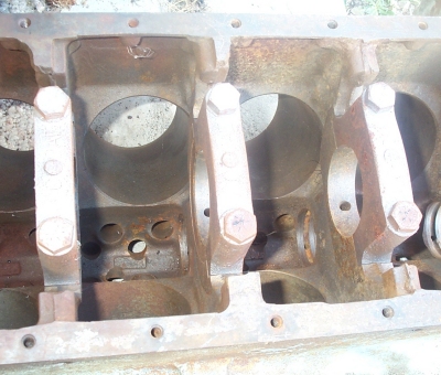
 The 427 Sideoiler engine has an additional oil gallery added to the lower drivers
side of the block. This change was introduced about the time that the 427 Single Over Head Cam (SOHC)
engine was first made. Note that this gallery required the relocation of the Drivers side motor
mount boss 1/4 inch higher. The bolt pattern is different because the lower bolt on a standard block
ends up in the side oil gallery location as picture at the right shows. Marine 427 versions of the
Sideoiler did not have the Sideoiler galleries drilled - this cuts through the lump cast in these blocks
for the side oil gallery. They were drilled for top oiling and the motor mount bolt pattern was the
standard one so they could not be successfully converted to a Sideoiler.
The 427 Sideoiler engine has an additional oil gallery added to the lower drivers
side of the block. This change was introduced about the time that the 427 Single Over Head Cam (SOHC)
engine was first made. Note that this gallery required the relocation of the Drivers side motor
mount boss 1/4 inch higher. The bolt pattern is different because the lower bolt on a standard block
ends up in the side oil gallery location as picture at the right shows. Marine 427 versions of the
Sideoiler did not have the Sideoiler galleries drilled - this cuts through the lump cast in these blocks
for the side oil gallery. They were drilled for top oiling and the motor mount bolt pattern was the
standard one so they could not be successfully converted to a Sideoiler.
The SOHC block had one change. An oil drain tube was added at the lower rear of each deck.
The only other change that was significant was the clover leafing of the cylinder walls on the 427. The upper left and right and lower left and right portions of the cylinder walls were thicker than the rest of the cylinder walls.
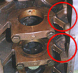
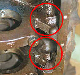
When the 428 CJ engine was introduced the main bearing webs were improved. These pictures show this change better than words can explain it.
Other changes
The casting numbers, such as C4AE, C5AE, and C6ME, on the passenger side of the block disappear Some time after Jan of 68 and then reappear in the 1970's. Other casting marks commonly seen are DIF and CF. These identify the foundry. All FE blocks until 1972 had 352 cast on the front drivers side of the block. After 1972 most FE blocks had an upside down 105 cast there instead, however, some blocks still used the 352 including the 427 service blocks. The casting date is on the bottom of the block at the oil filter adapter pad.
Minor changes such as recessing the head bolt holes so the head bolts dont lift the edges of these holes were made but are overlooked by most people. At various times Ford didnt put a casting number of the side of the block (on the Drivers side in front of the motor mount area). In 1971 some vertical ribs appeared in the area where the casting number used to be. The FT engine had thicker cylinder walls and the CJ main bearing saddles.
Despite numerous claims no high nickel blocks were ever cast by or for Ford.
Block Drain Plug Previous Topic Next Topic Top
How do you remove a seized drain plug from block?
First, you can crack cast iron by getting it too hot and not cooling s-l-o-w-l-y. Don't get too crazy with heat on cast iron blocks. Heat the plug nice and red if possible then spray it with water until cool.
The candle wax trick works. I have done it many times. Lay your block over on its side and apply some heat. Get it fairly hot, but not red, then melt some of the wax around the plug. It will flow in around the rusty threads. Try again with your extractor and I'll bet it comes out. May need to repeat or turn the heat up slightly.
Don't heat around the plug, heat the plug straight on, right in the center- it'll expand in the threads, and crush the rust in the process. After that is a great time for PB Blaster or wax - should come right out.
Block Plate Previous Topic Next Topic Top
1962 and older FEs did not have a block plate. They have a starter seal.
Block Markings - Sand Scratchings Previous Topic Next Topic Top
Found either a "4" or a "5" in the lifter valley at each cylinder painted in yellow paint. What does this mean?
Shoe Precise bore diameter marking, or cylinder grade marking. Here is a link to 427 cylinder grading codes through 1967 or so. The codes were changed slightly for all Ford engines in 1968 or so. Shoe
Some additional comments on the forum.
Blocks Previous Topic Next Topic Top
Center oiler (or top oiler): 1963-1/2 thru 1965-1/2
Side oiler: 1965-1/2 thru 1967, then 1968 in Cougar only (w/hydraulic lifters)
Cam Bearing Installation Previous Topic Next Topic Top
Cam bearing location in a "standard oiling", usually called either a top oiler or center oiler, block where the oil passes around the camshaft before going the mains. Is the location of the oil hole in the cam bearing either at 3 o'clock or directly inline with the oil galley leading to the crankshaft important?
Shoe: I believe the oiling hole should be located at least a couple dozen degrees prior to the 135 degree (hole in the cam bearing sort of points above the oil filter bracket.) [This is the four o'clock position.] Thus the camshaft rotates on the wedge of oil developed at the oil hole so it can hydrodynamically compress and float the cam journal through both banks of lifter loading. Shoe
I have several original never rebuilt blocks, bearings 2-5 were at 3 o'clock. Guess where I installed my new bearings.
Camshaft Plug Installation Previous Topic Next Topic Top
The camshaft plug at the balck of the block goes in backwards to the way most other plugs are installed. You shold no be able to see the plug walls when it is installed.
Casting Date Decoding Previous Topic Next Topic Top
How to I decode a Casting Date?
Ford's date code is a number followed by a letter and then one or two more numbers. The first number is the year but for FE parts cast in 1970 and later two small dots appear over the year character. The second character is the month but the letter 'I' is not used so the months are an 'A' for January through 'M' for December. After the month is the day of the month which is either one or two characters.
Casting Number Decoding Previous Topic Next Topic Top
How to I decode a part or casting number?
First most published lists of casting numbers and their definitions are incorrect. This explanation by Hawkrod tells us how casting and part numbers numbers were actually assigned.
Hawkrod: Casting numbers can be confusing and there is a lot of misinformation out there which makes it worse. The casting (or engineering) number indicates a lot of information. It does not always indicate what a part was used on but it does indicate what it was originally designed for. The engineering number consists of three parts, the prefix the base number and the suffix.
Please keep in mind that the following explanation applies only to about 1962 and newer parts. The system used was adopted prior to that but there were variables such as only three numbers in the prefix or using engineering numbers as part numbers but those items rarely come up in normal conversation. The current system was adopted in 1959 and was based on an earlier system that Ford used. By 1958 Ford knew they needed a new system and they started using one designed by a former GM employee but because existing workers could not cope with the change it was quickly discarded (you may often see casting numbers like 5752614, this means it was made in the 58-59 time frame).
I will use the engineering number C9AE-9425-B as an example as it makes it very easy to explain: The base number is the easiest to understand because it always means the same thing, it is what the item is. In this case it is 9425 which is always an intake manifold. It does not matter if it is a 1962 6 cylinder or a 2005 Ford GT, a 9425 is an intake manifold. The only potentially confusing part of this is there are sometimes other numbers that can also identify the same type of item and in this case a 9424 is also always an intake manifold.
The next easiest part of the engineering number to understand is the prefix. In this case C9AE. This really is basic. The character is the decade A is 40's, B is 50's, C is 60's, D is 70's and so forth. The next digit is the year, in this case 9 so C9 means 1969. The third character is the model line that originally was billed for and the part was originally developed for, not what it was actually used on, but what it was developed for. A is full size car, D is Falcon, Z is Mustang, etc. There are a lot of codes and depending on the year it can mean something else. For example C was Remanufactured Parts from 1966-75 and then became Capri in 1979. The fourth slot of the prefix is usually where things go south for people because Ford did not always treat this the same. If the fourth slot is actually part of a number on a part, it identifies the engineering department responsible for the design of the part. F is fuel and ignitions, E is engine, B is body, etc. However, if the fourth slot is on a piece of paper, a box or a tag and is a Z you are no longer looking at an engineering number, you are looking at a part number. I will give more detail on this after I explain the rest.
Now, finally in the engineering number, is the suffix, it is the last letter and it is often called the change code. Unfortunately it does not specifically note a change but it can. It can be more properly called a version code to identify the specific version of a particular item. They always start with A so C9AE-9425-A would have been the first intake manifold designed for a 1969 Ford full size car, C9AE-9425-B would have been the second intake manifold designed for a 1969 Ford full size car, etc. This does not mean that B is a change in design of A. The A version can be for a totally different application and in this case is, C9AE-9425-A is 2 barrel intake manifold for a 429 Ford, while C9AE-9425-B was for a 390 Ford. Depending on the part the suffix can be a revision of a part but a revision can also be noted as C9AE-9425-B1 so revisions can be confusing and it takes some experience or a pile of books to figure out sometimes.
What all of this means is that a C9AE-9425-B is an intake manifold that the full size car department paid the engine department to design in 1969 (I use the word paid as the work was "billed out" for accounting purposes). This does not mean that a 69 Ford car is the only place you will find it because after a part already exists it can be used by any line and it also does not mean that the department that paid for it even used it. For example a C9OE-8509-G is a water pump pulley for a 1970 small block. It was designed in 1969 but never used that year (and actually won't fit a 69!). There are also examples where the next years parts are released early such as 1968 302 blocks and intake manifolds that were used on the late 1967 289's. There are even examples of next years parts that were used on this years cars and then dropped in favor of a new design such as a DOZA-3108-B and DOZA-3107-B spindles used on some 1969 Shelby Mustangs and 1969 Boss 302 Mustangs but not used on 1970 Mustangs (the 1970 used DOZA-3108-C and DOZA-3107-C which are examples of where the suffix does note revisions!)
There are a couple of other caveats about the numbers you see that you may need to know. First would be assemblies, very often a part is made from several parts. The best example I can come up with of this is a distributor. These are made from many parts and each part has an engineering number as does the assembly. I use this example because most distributors (except for FE style 352, 360, 390, etc.) have two engineering numbers showing. One number is usually on the lower body running top to bottom and is a number like C80F-12131-A. 12131 is a base number for a distributor housing. If you look closely at the same distributor you will also see an engineering number near the top running horizontal and it will be something like C9ZF-12127-E. 12127 is the engineering number for a distributor assembly. This difference can be very confusing and is the reason that most Ford FE engine casting number charts are wrong. The original chart was done by somebody who was reading books and not looking at parts and saw a whole slew of number that never actually appeared on parts! Very often a base part will have a number but will be assembled with different components and these parts do not always have an assembly engineering number on them. In this case all the assemblies would show the exact same engineering number but the books show a whole bunch of numbers. The most common example that I am aware of is the C8AE-H cylinder head for an FE. This single number is associated with a dozen or more assembly engineering numbers. People often get confused because the printed lists such as in Steve Christ's How to rebuild your big block Ford and George Reid's pocket guide contain numbers that never actually were cast into heads. Unfortunately they both copied a list of numbers that contained numbers from books not from parts!
There are also parts sold through Ford subcontractors such as Shelby and Holman Moody that used Ford like part numbers as it was easier for them. You will see Shelby intake with a S2MS number and this decodes just like a Ford number except 2 is not the last number of the year, it is the second year. So S is Shelby, 2 is second year, M is Mustang so it is for a 1966 Mustang. In 67 they changed the year number to reflect the actual year so 67 parts are S7MS. Holman Moody is the same but starts with HM and the number is the year so HM5 is 1965.
Finally we get to part numbers. These are numbers used by the Ford Replacement Parts and Service Division to sell replacement parts. Very often these numbers are the same as the casting number but have a Z in the fourth slot. The Z simply notes it was entered in the parts department system. This number will not be cast on the part but will be on the label or box. For example a C9AE-6312-B engineering number is a C9AZ-6A312-B part number. Unfortunately the part number does not always so easily relate and a C8AE-6312-E engineering number is a D3TZ-6A312-A part number because it was not available as a service part until 1973 even though it was used in 1968 (Ford sold a three groove pulley to replace it as it is the same but the original had two grooves). I realize this is long winded but I hope it helps people understand the Ford numbering system. Tom Cherry AKA Hawkrod
Clutch Fork Pivot Previous Topic Next Topic Top
The pivot point on my bell housing does not have the slot in it for the clip on the back of the clutch fork. Can the pivot point be switched out for one that does?
Bobby Spears: You can switch the pivot for a later one. I just swapped them on the Falcon I am working on. I had to drill out the rivets and then just used two bolts. Bobby Spears
Distributor Dwell Previous Topic Next Topic Top
Forum ThreadDistributor Gear Roll Pin Previous Topic Next Topic Top
Forum ThreadDistributor Vacuum Advance Adjustment Previous Topic Next Topic Top
Which way do you turn the vacuum advance adjustment?
Bobby Spears: Turning it counter clockwise increases the spring pressure and it will advance less and drop off faster to not have what is called a tip in ping when you mash on the loud pedal. Bobby Spears
Emissions 360 and 390 Truck Engines Previous Topic Next Topic Top
The 390 truck engine of the 1970s uses the 410 piston to reduce the compression ratio. This piston often has 410 on the side of the piston near the pin boss. The chart at the right shows that this increase the deck height to 0.120. When you add a head gasket thichness of 0.042 this effectively eliminates quench and greatly reduces power. The only solution is change the pistons.
Likewise he 360 truck engine of the 1970s uses the 390 piston to reduce the compression ratio.
This piston usually has 390 4V on the side of the piston near the pin boss.
Engine Indentification Previous Topic Next Topic Top
Determining which displacement you have is impossible by just checking the various block and head casting numbers as the casing numbers are almost always shared by every engine produced in any given year. If you can remove some spark plugs and if the engine will rotate then you can check the stroke.
You can check the stroke and pin down the possible displacement without removing a head. Get a straight 12 inch piece of coat hanger wire. Get a magic marker. Remove the number 1 and number 4 spark plugs. Turn the engine over until the timing mark is at TDC. Put the wire in the number 1 spark plug hole with wire resting on the top of the piston. Make a mark on the wire even with the lip on the valve cover. Now move the wire over to the number 4 cylinder and mark the wire again. Measure the distance between the two marks. (Thanks to John Wilkerson for giving me the idea for the stroke checking.)
For those that don't know: 3.98 is the stroke for the 410 and 428 engines; 3.78 is the stroke for the 390, 406 and 427 engines; 3.5 is the stroke for the 330(FT), 352 and 360 engines and 3.3 is the stroke for the 332 engine.
FE blocks have a casting date on the bottom of the oil filter mounting pad. There also may be a casting number on the passenger side of the engine just below and to the front of the front freeze plug. The casting number for the heads is between the center two spark plugs. The head casting date is just inside the valve cover rail at the center of the head.
So the best you can hope to determine is the casting date and the current stroke. This will give you some idea about the size of the motor but without tearing it down there is no way to know the actual displacement.
Engine Paint Colors Previous Topic Next Topic Top
All 427's from 63 through mid 65 were black. The block, heads, timing cover, and water pump all were painted black. 390s had gold valve covers; 427s chrome ones.
Black was the paint used in 1965 and earlier motors. The first year for blocks to be painted Blue was 1966. 428's were all corporate blue as they came out after the switch. Ford painted the 427 Black until mid year 1965 then switched to Dark Ford Blue from mid 65 on. Your pulleys should be a satin black. The pulleys should be painted matte black.
DisplacementEngine Size Previous Topic Next Topic Top
Note 1: The calculation is Radius x Radius x Stroke x numbers-of-cylinders x Pi. Or by
multiplying the Half-the-Piston-Diameter (Radius) times Half-the-Piston-Diameter times the Stroke times
the Number-of-Cylinders times Pi (3.14159). An equivalent forumla commonly seen is Piston-Diameter
times Piston-Diameter time Stroke times 0.7853975.
Note 2: The numbers in blue are the factory bores or strokes and the resulting displacements.
(Yes, I know these don't match our common names of 390, 427, etc. Blame this on the Ford Marketing
Department.)
Engine Weight Previous Topic Next Topic Top
Bare FE block - approximately 200 pounds.
659 pounds for a stock 427, aluminum intake, single 4BBL, long tube cast iron headers, complete ignition, starter, alternator, 28 pound flywheel, water pump, fan, belts pulleys, fuel pump. A complete break down is at fordcustom1958.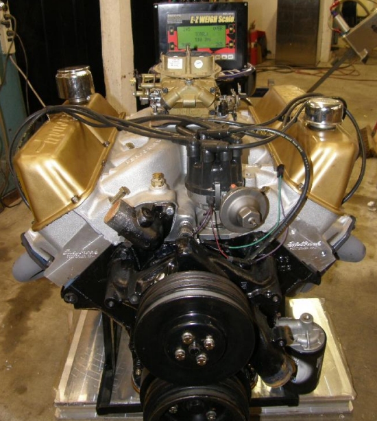
Jay Brown: My 390 stroker motor (right)is on a pair of circle track scales. Weight is 510
pounds with everything except the alternator and brackets and includes a cast iron water pump. (The
stand supporting the engine is not included in the weight; it was tared out before the engine was put on
the scales.)
If you have an aluminum water pump, you should be right about at 500 pounds. Jay Brown
Exhaust Manifolds - GT Previous Topic Next Topic Top
Are the FE GT exhaust manifolds and motor mounts the same between the Fairlanes and Mustangs?
Hawkrod: '66 Fairlane/Comet is all by itself. '66 is different because the drivers side has a different bolt pattern than the '67-69 but the '67-69 was the same for any model that used a 14 bolt manifold at the time it was made. What I mean by that is a '67 Mustang is the same as a '67 Fairlane and a '69 Mustang is the same as a 69 Fairlane but as I noted, '67 is different from a '69.
Right hand exhaust manifold is different but has the same casting number. '67 and early '68 have a spacer or valve on the right side that was eliminated in late '68 and '69's so the end of the manifold is machined differently. '67/8 is flat and '68/9 has a large bevel for a donut. If you try and use a '68/9 with a spacer it will blow the gasket out in no time. Hawkrod
FE definition Previous Topic Next Topic Top
What does FE mean?
This is a question that has been discussed and debated at length on the forum. I think it means Ford Edsel engine.
In 1958 Ford introduced two new engine families. Ford used the 332 and the 352 displacements and Edsel used the 361 displacement of the smaller of these engine families while the Mercury used the 383, Edsel used the 410 and Lincoln used the 430 displacement of the larger of these engine families. (Later this engine grew to 462 cubic inches in the Lincoln.) Thus FE stands for Ford Edsel. MEL stands for Mercury Edsel Lincoln. Both of these terms (FE and MEL) were commonly used in the mid to late 60s.
Others claim FE means Fairlane Engine. Fairlane was a model name for the full size Fords from 1955 through 1962. Fairlane became a mid size car in 1963 and the FE would not fit into this smaller car in 1963. The FE was not used in the Fairlane again until 1966. A new V8 engine family was introduced in 1962 the 221 and 260 engine which grew to 289 and later 302. To me this was the Fairlane engine.
Others claim FE means Ford Engine. You find FE and FT in common use with FT meaning Ford Truck engine.
Flex Plates and Flywheels Previous Topic Next Topic Top
Flex plate - 15 9/16" diameter - 184 tooth
C6AE-6375-B and C6AE-6380-B are both 428's including CJ's but C6AE-6380-C is a small block 28 ounce flywheel
Freeze Plugs Previous Topic Next Topic Top
FEs use 1-49/64" plugs, not the 1-3/4" ones. There are two types, heavy long wall ones and thin plugs with no walls. Use the long wall ones. Make sure the core plug holes are clean. Paint the back of the plugs with Indian Head Gasket Shellac. This practically stops corrosion from starting. Paint the freeze plug hole and then install.
Front Cover Installation Previous Topic Next Topic Top
Bill Ballinger: The front cover must be aligned to the crankshaft in order to prevent premature wear of the front seal. You should have the seal installed and slide the crank shaft spacer into place before tightening the front cover bolts. Some people wrap the crankshaft sleeve with a layer or two of electrical tape. Insert into sleeve and use it as a guide so that the cover is going on straight by feeling for any binding at the seal surface as it is being tightened into place. Note: some bolts require sealer because they go into the water jacket. Remove the sleeve and tape then re-install the sleeve. Bill Ballinger
Harmonic Balancers Previous Topic Next Topic Top
Hawkrod: All FE harmonic balancers (vibration dampeners) are neutral balanced - they will work on any FE. If your balancer has a fan belt groove in it then it is a 67 and older unit. The later ones (1968 and up) use a different bolt pattern for the crank pulley.
The 67 and older balancers can swap with the 68 and newer ones as long as you have the correct pulley for the balancer. The rest of the engine pulleys and brackets will line up just fine (unless you have one of the very few oddballs like a 61-64 T-Bird). The 68 and newer balancers are considered better due to the larger mass.
The 428 SCJ used a small hatchet behind the balancer. For all other 410s and 428s the inbalance is on the flywheel. The 428 SCJ balancer will work fine on any FE (but don't use the hatchet). Hawkrod
Head ID Previous Topic Next Topic Top
List of head casting numbers, original application, valve sizes, amd some comments.
Early heads had machined combustion chambers. These heads had slightly smaller combustion chambers that the heads with the as cast chambers but sharing the same casting numbers.
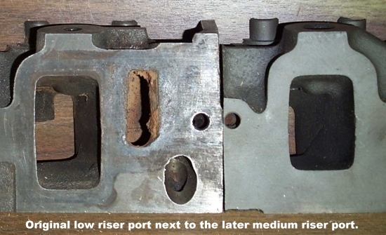 The C6AE-R head is the splitting point between original
head design and the later emission heads. All heads before the C6AE-R had the tall intake ports.
The old style Low Riser intake port had the floor of the port raised to reduce low speed emissions.
This raised floor matched that of the Medium Riser head. See the photo at the right.
Only the 427 and 428CJ heads used the large intake port head after 1966.
The C6AE-R head is the splitting point between original
head design and the later emission heads. All heads before the C6AE-R had the tall intake ports.
The old style Low Riser intake port had the floor of the port raised to reduce low speed emissions.
This raised floor matched that of the Medium Riser head. See the photo at the right.
Only the 427 and 428CJ heads used the large intake port head after 1966.
Heads used in 427 marine and industrial applications had the standard 2.03/1.56 valve sizes.
Some C6TE heads were used on the car production line early in the 1966 model year.
The C6TE is a pre-emissions style head. Same as C4AE-G except it has thermactor emissions bosses and not the diagonal exhaust bolt bosses.
All exhaust ports were lowered on all heads (except on the 427 MR, HR and TP) starting in 1966 to accommodate the mid-size Fairlane shock towers. This mismatch is discussed in the Headers Leak topic.
All heads starting with the D2TE-AA had induction hardened exhaust valve seats.
The C8WE-6090-A heads were race oriented parts distributed directly to Ford factory sponsored competitors with the 428CJ Mustang program in mid 1968. The intake port opening measures to stock CJ size but it is raised in the casting about .200" both top and bottom. The combustion chamber volume is around 72cc. The exhaust ports are the standard 8 bolt pattern.
The C8AE-6090-J heads were also used on some 427 low-riser applications. They can have 8, 14, or 16 bolt holes in the exhaust face.
- 428 Cobra Jet Cylinder Head Specifications C8OE-6090-N, Part number C8AZ-6049-K
- Combustion chamber volume 72.7 - 75.7 cc
- Intake valve diameter 2.082 - 2.097 inches
- Exhaust valve diameter 1.645 - 1.660 inches
- Intake Valve Seat - 30 degrees>/li>
- Exhaust Valve Seat - 45 degrees>/li>
- Intake port size 2.34" x 1.34"
- Exhaust port size 1.84" x 1.34"
- Spark plugs Autolite BF-32
- Three step head bolt torque specs 70, 80, 80-90 foot-pounds
Headers Leak Previous Topic Next Topic Top
Shoe: Ford first shrunk the FE intake runners and added thermactor exhaust
reactor bosses in 1966, and lowered the exhaust port exit location at the same time. All FE
production car heads got these changes except for the C6AE-R heads often found in any mid-late 1966 FE,
and except for 428CJ and 427 heads. The intake was shrunk to increase runner velocity to improve
exhaust emissions. Thermactor bosses were added to allow camshafts with more overlap (GT and CJ) to
pass emissions. (Emissions came to the fore in 1966 with strict California and New York emissions
laws, and went nationwide in 1968 when these specifications became Federal emissions laws.) The
exhaust port exit was apparently lowered to help keep the all-new 1966 Fairlane/Comet exhaust manifold
far away from the shock towers.
 I suspect ease of assembly-line installation was the primary
reason, and they were apparently a bit conservative on the design. This would not be a compatibility
problem on Galaxies or pickup trucks, since these log-type exhaust manifolds already had oversized exhaust
openings to fit either pre-emissions heads or emissions-type heads. Sadly, the new Fairlane exhaust
manifold will only port match to these emissions-era heads, as early heads with the higher-positioned
exhaust port may sometimes leak out the top of the manifold.
I suspect ease of assembly-line installation was the primary
reason, and they were apparently a bit conservative on the design. This would not be a compatibility
problem on Galaxies or pickup trucks, since these log-type exhaust manifolds already had oversized exhaust
openings to fit either pre-emissions heads or emissions-type heads. Sadly, the new Fairlane exhaust
manifold will only port match to these emissions-era heads, as early heads with the higher-positioned
exhaust port may sometimes leak out the top of the manifold.
This brings us to your issue, since many headers utilize the weld bead on the header flange to crush the header gasket. Unfortunately, the weld bead on these headers will usually not crush against at the lower edge of the port, and the gasket leaks, causing backfires, and noise. Fortunately, some truck headers use a low-positioned flange that does match the emissions heads (but doesn't match the pre-emissions heads, which is a problem on 1965 pickups, the first year for FEs in pickups, since 1965 trucks have high exit exhausts and the headers may leak along the top.
Confusing, undocumented, and frustrating, but once figured out not a big deal. I would advise elongating the bolt holes in your headers and gaskets to permit vertically offsetting the ports so that the gasket is crushed along the full perimeter. Alternately, weld a bead along the base of the header and grind it flush to the existing weld bead. Beware many exhaust gaskets are still asbestos, particularly the cream colored ones, so be careful with any gasket debris.
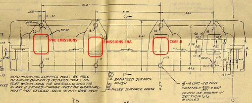
This larger version of the above Exhaust Port drawing incudes the bolt pattern. All heads with the four additonal bolt bosses can be drilled for the additional bolts but be do not drill so deep that you get into the water jacket. Shoe
Head Gasket Instalaltion Previous Topic Next Topic Top
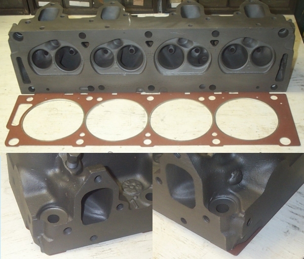
Bill Ballinger: Water outlets in the ends of the gaskest must be at the rear
of the engine on both banks. Water will not flow properly if these openings are not put to the rear.
The gasket installation can be checked after the heads are installed. The top of the picture
at the right shows a head and gasket. In the bottom left of the picture only a little bit of gasket
is showing; this is end of the gasket with the opening. In the botton right of the picture much more
of the head gasket can be seen; this is the end without the opening.
Bill Ballinger
Intake Manifold Installation Previous Topic Next Topic Top
Bill Ballinger: Intake Manifold Installation. You should use a pilot, such as a cut down distributor body, to align the manifold during installation. Use of this pilot will make front-to-rear and side-to-side alignment easy. Mis-alignment will cause side loading of the distributor shaft. Some blocks have an alignment dowell in the front wall of the block that does this alignment function. (Many after market intake manifolds are not machined for this dowell so it must be removed.) Bill Ballinger
Intake Manifold Splash Pan Removal Previous Topic Next Topic Top
How do you remove the "pan" on the underside of the manifold? Is there a way to take it off without destroying it?
Bob Hasty: It only looks like it is riveted on. Gently tapping a
sharp chisel under the rivet heads will extract without breaking them. If you tap them counter-
clockwise they will back out on their own as they are not rivets so to speak. They have a twist on
them so you can cut a slot into the top of the head and use a screw driver or use a combo of a chisel and
punch to turn them out. A good swift whack with a hammer sets them back in place once you have
cleaned them out. Bob Hasty
Don W: Use a Dremel tool and cutoff wheel to slot the heads. Use a screw driver or impact screw driver to back them out. You can then tap the hole or press the original screws in, use Locktite to secure them. Don W
Main Cap Walk Previous Topic Next Topic Top
Does cap walk affect only the 1st main cap on 2 bolt blocks?
Shoe: No. Walk only affects the #2, #3, and #4 caps. The #2 and #4 cap are stressed by both high torque and high RPM, and the #3 cap is stressed only by high torque (supercharging). The reason the center three caps can "walk" is due to the offset bulkheads between the driver and passenger cylinder banks. When the center three maincaps are "loaded" while racing, the bulkheads cyclically flex oppositely at each maincap bolt, causing the maincap to momentarily flex backward on the driver bulkhead and forward on the passenger bulkhead, effectively twisting the cap in the registers. This imparts the name "walk" to the twisting motion, and with sufficient walk the block and caps can "fret" where they contact each other.
If you find a maincap fits loosely in a block, and is no longer an interference fit during install or removal, the cap has probably "fretted" against the registers until the machined surfaces have worn. loose-fitting maincaps should be thought of as "worn out" due to cap walk, though it is possible an unworn cap fits loosely in the registers because the block has cracked at the main bearing oil feed hole.
The front cap can bend forward under severe load or RPM, but the flex is actually in the block's bulkhead, not the cap itself. The front cap remains untwisted in the register during the flex, so the front maincap faces never "fret" against the blocks clamping faces or registers.
The same goes for the rear maincap, except the rear maincap is so solidly mounted into the block the slight flex under load is simply not a stress issue. JMO Shoe
Myths - Misconceptions and Misunderstandings Previous Topic Next Topic Top
Things that people beleive that just aren't true.
Rear Main Bearing (Crank) Seal Previous Topic Next Topic Top
What makes the new rubber rear mains better than the rope style?
Shoe: The factory asbestos seal works well, though it requires the oiling helix be cut into the crank to "guide" oil back into the engine. It also adds measurable friction to the engine. The split neoprene seal does not require the oiling helix, though there are rare occasions when the split neoprene seal doesn't initially seal, and this can be a pain to correct. Neoprene seals are very low in friction. Shoe
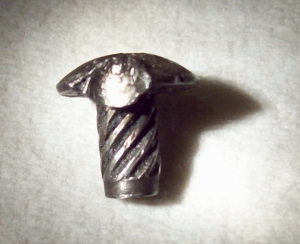
Timing Chain and Gear Installation Previous Topic Next Topic Top
Bill Ballinger: When changing a timing chain and gears you will find that virtually all of the replacement top timing gears have a thicker mounting flange on the back of the sprocket. On the original installation, many FE's had a spacer washer between the cam and gear. It will be similar in shape to a round horse shoe, open on one side. THIS SPACER MUST BE REMOVED BEFORE INSTALLING NEW GEAR OR SERIOUS ENGINE DAMAGE CAN RESULT UPON START-UP. If the top timing sprocket you have taken off is thinner than the one you are replacing it with, the spacer is in there and may be difficult see. Look in the cam retainer on the front of the cam, it will usually be hiding there. If the "thick" gear is installed, the camshaft will be pushed back into the rear cam plug, and the lobes relationship to the lifters will be wrong. This can destroy the cam and lifters in a matter of seconds and the metal particles will destory the oil pump, crank and bearings shortly thereafter. Bill Ballinger